Chilled Beam Energy Study

Government wanted 20% improvement in energy efficiencies, settled for 9%, could have 22% today for commercial buildings air conditioning.
On the 29th July 2013 Dr. Allan Jones of EDSL (Environmental Design Solutions Ltd) participated in an Energy Seminar at "The Building Centre", London alongside Michael Ainley Managing Director of Frenger. EDSL Tas is one of two Government accredited energy simulation modelling software providers for Part L Energy Compliance Calculations in the UK and the EDSL Tas software is adopted and used in over 20 different countries worldwide.
Given the difficulties of establishing a true and fair comparison to all 3 different competing air conditioning technologies (as most buildings differ in size, shape, construction and location) EDSL had to ensure that a worst case scenario location in the UK for free cooling possibilities was modelled (London) and an average location central to the country was also modelled (Birmingham).
The weather data used was an average year over the past 20 years as published by the Chartered Institute of Building Services Engineers (CIBSE).
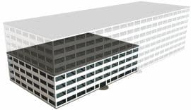
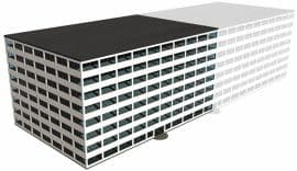
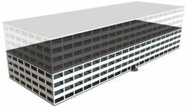
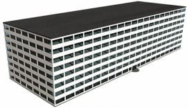
4 different size and shape building were modelled (7000m2, 14000m2 and 28,000m2 consisting of 4 and 8 stories in height) using EDSL Tas software version 9.2.1.6 for dynamic thermal performance simulation modelling.
All 3 Air Conditioning system set ups were based upon the NCM (National Calculation Methodology) Guide for floor plate zoning and heat losses and heat gains, plus respiratory requirements for the occupants, that being 12ltrs/sec/person. Each system had identical heating and cooling loads and plant system set ups.
The 3 systems modelled were:-
- VAV Fan Coil units with EC motors.
- Active Chilled Beams
- Passive Chilled Beams (95% Convection / 5% Radiant)

As can be seen from the chart above the system that consumed the most energy was used as the bench mark (VAV Fan Coil with EC motors) as being 100% of the cost for energy consumption and the other systems displayed as a percentage of the bench mark. The above chart shows on average there is potentially 17% energy cost savings by use of Passive Chilled Beams in the exact same building modelled and likewise 22% energy cost saving with Active Chilled Beams.
The energy costs were based upon 13p per kw/hr for electricity and 5p per kw/hr for gas.
In summary Dr Alan Jones (Managing Director of EDSL) has stated:
"The analysis we have undertaken on behalf of CBCA/FETA has been impartial with regards to any particular piece of equipment type. We have modelled the fundamental physics of the processes involved to develop an insight into the relative contributions to energy use of each of the component parts."
The central plant components are common to all system configurations, so this aspect provides a level playing field. This central plant consisted of a chiller and DACs free cooling combination for heat rejection and a gas fired boiler for heating. Fresh air conditioning for temperature and humidity consisted of a typical VRF heat recovery DX circuit.
Main AHU fan SFPs was the same for all systems at 2.1W/l/s. In common practice and due to cost considerations there may be some variation between the VAV fan coil and the active chilled beam systems due to a typical maximum of 100pa additional pressure for induction of room air as active beams do not have any secondary fans. This would be of the order of 0.1W/l/s, which would not have a significant impact on energy use.
In the study the VAV fan coil terminal fan had an SFP of 0.25W/l/s at 100% volume flow rate and was typically half this with VAV turn down to minimum fresh air for respiratory requirements , that being 20% of the design volume . This was not necessarily an ideal combination. We have since the issue of the energy study comparison ran off an alternative simulation with a turn down to 60% air flow which is more typical and have used an enhanced SFP of 0.2W/l/s for the VAV fancoil units to best represent the best pro forming VAV fancoil units available, this resulted in an overall reduction in total system fan energy of 2.5% and netted out at 1% overall reduction in the VAV fancoil systems energy consumption, thus narrowing the gap from approximately 22% to 21% more energy consumption associated with VAV fancoils as opposed to Active Chilled Beams.
The fundamental difference in the specifications was chilled water supply temperature which was 6C -12C for the fan coil and 14C-17C for the active chilled beam. We were asked to use these temperatures to represent the most widely used practice and to create a typical “base line” as both systems (VAV fancoils and Active Chilled Beams can respectively elevate their chilled water flow temperature from their respective “base lines”. The improvements in chiller COP and amount of DACs cooling offered by the high chilled water temperature is and was the fundamental difference in energy consumption for the alternative systems. The VAV fan coil terminal fans are so efficient that they have a secondary effect on relative energy use.
"I believe the energy use debate is mainly down to chilled water supply temperature."
Also presenting at the Building Centre was Andrew Jackson and Michael Ainley of the CBCA (Chilled Beam and Ceiling Association) whom are a specialist section of the HEVAC and FETA (The Federation of Environmental Trade Associations).
Michael Ainley (Managing Director for over 18 years of a company specialising in chilled beam technology both UK and overseas) said "The evidence regarding how much more energy efficient Chilled Beam Technology is to other forms of air conditioning is long overdue. If the UK is to achieve a carbon neutral state by 2019 then the information in this independent study is most useful for specifiers and comes at a time when the UK Government has announced that an uplift in energy efficiency standards for non-domestic buildings (i.e. Commercial Buildings) of 9% is required for the new Part L Building regulations which is due to be implemented October 2013 and to come into force by April 2014.”
As stated by Dr Alan Jones of EDSL it’s “fundamental physics” and the bottom line is “mainly down to chilled water temperature”.
In essence the higher the chilled water flow temperature, the less energy consumed as can be seen by the pie chart below, the chiller is the main energy consumer for all 3 systems.

The reduction in chiller energy consumption is twofold.
- Firstly, the higher the chilled water flow temperature, the greater the COP (Coefficient of Performance) for the chiller (see graph to the right). i.e. at 6°C chilled water flow, 1Kw of electricity provides 4Kw of cooling energy and likewise at 14°C chilled water flow, 1Kw of electricity provides 4.5Kw cooling energy.
- Secondly, the higher the chilled water flow temperature for the system, the greater the opportunity of free cooling (i.e. the outside ambient air temperature is cooler than the system chilled water flow temperature). This is the reason as to why Birmingham used less energy for each building modelled as opposed to the exact same building modelled in London (London slightly warmer outside ambient than Birmingham).

It is fair to say that all 3 systems can raise their chilled water flow temperatures from their traditional norm that being 6-12°C F&R for Fan Coils and 14-17°C for Chilled Beams and all 3 systems will reduce overall total system energy consumptions.
That being said there are limitations as to what flow temperatures can be achieved commercially for each of the 3 different systems.
The commercially sensible maximum chilled water flow temperature that a VAV Fan Coil system could be raised to would be around 10°C as anything above this would involve dehumidification of the air at the Air Handling Unit (AHU) which would not only add cost to that system but would further compound the cooling performance of the Fan Coil system given that Fan Coil systems are designed to condense and that forms part of their cooling capacity. This issue coupled alongside the smaller ΔTK (difference between mean water temperature and design room temperature) would yield the less cooling performance from each Fan Coil, hence more Fan Coil units would be required at increased capital expenditure.
Similarly Chilled Beams work to this principal of ΔTK and as such 17°C flow would be the commercially sensible limitation required for the cooling requirements of buildings verses capital costs, although Chilled Beam technology has always been designed to operate above dew point and no contribution from condensing for it’s cooling performance.
In summary if all 3 systems push the boundaries competing for energy efficiency the sensible commercial limitation would be circa 10°C flow for VAV Fan Coil systems and 17°C for Chilled Beam systems.
The effects of raising the chilled water flow temperature from the historical norm for all 3 systems are detailed below.

This article is a simplistic summary of the findings of an "independent" and "in depth energy consumption study" for 3 different air conditioning systems consisting of 24 sets of comprehensive output data as produced by EDSL.
For more specifics of the input and output data, systems set up, this is available as an 11 page PDF download from www.feta.co.uk/associations/hevac/specialist-groups/chilled-beams--ceiling-association.


